68
7X24 MAGAZINE FALL 2014
used to convert the DC power from
the battery to create AC power to
support the load when the utility
fails. Normally the inverter is
operating in a stand-by mode, with
the battery charger maintaining the
batteries. Should the utility power
go out of specification, the inverter
powers the load, drawing energy
from the battery.
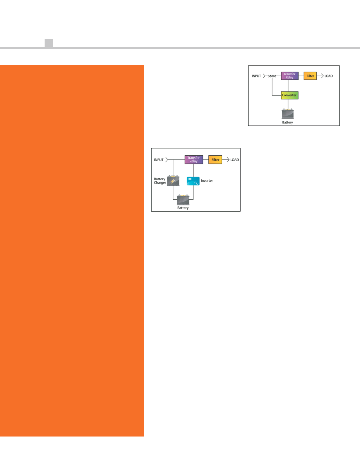
Figure 1. Passive standby UPS topology.
While this topology gets high
marks for simplicity of design, the
limitations of the design—such as
the lack of power conditioning,
brief power interruption during
transfers, or generator compatibility
(e.g. gensets generally have poor
step-load capabilities)—make it
unsuitable for three-phase
applications. These types of UPS
modules are typically only applied
to single-phase (workstation-level)
loads.
lIne-InTeRACTIve
The next step upward is the line-
interactive topology (Figure 2). It
resembles passive standby, but
inserts a transformer or inductor in
series between the utility power
source and the load. This inline
inductor enables the UPS inverter
to “interact” with incoming power
and provide a measure of power
conditioning to the load, which also
helps with high and low input
voltage conditions.
Figure 2. Line-interactive UPS topology.
One major limitation of this
topology is that it cannot
completely isolate the critical load
from the input line without
operating on battery. Small
perturbations in frequency and
power quality can get passed
directly to the critical load.
Without electrical isolation,
common-mode noise also passes
right through to the load.
Like the passive standby topology,
line-interactive can be lower-cost
but effective, because it supports
the entire critical load during power
disturbances (for the duration of the
battery). Line-interactive may be
slightly less efficient, as result of the
incremental losses associated with
its power conditioning function.
While similar to passive standby,
line-interactive UPS systems are
capable of soft-loading a standby
genset, reducing the step-load
effects.
onlIne doUBle-
ConveRSIon
Online double-conversion
topologies (Figure 3) have emerged
as the preferred topology for the
data center, displacing standby and
line-interactive UPS systems in
network access rooms as overall
network availability requirements
rise. It is the only topology that
protects against the full range of
doeS yoUR UPS
PRoTeCT The loAd,
oR ITSelF?
Many UPS systems boast
reliability, but not all UPS
models are designed to protect
the connected equipment.
Your UPS should be able to
withstand multiple,
simultaneous power and
environmental events without
forcing a switch to bypass.
whAT To looK
FoR:
• Continuous-duty static
switch: Ensures maximum
fault clearing capability in
case of extreme overload or
downstream faults.
• No contactors in the bypass
path: Contactors are not
designed for high withstand
requirements.
• Redundant fans: Ability to
tolerate a minimum of one
fan failure before going to
bypass.
• High withstand rating
(100kA or higher): Allows
the equipment to stay online
during more severe short
circuit or circuit overload
conditions.
• Start a like-sized Power
Distribution Unit (PDU)
without transfer to bypass:
Keeps the system on
protected power when
additional distribution is
added.


