42
7X24 MAGAZINE FALL 2014
Modular Containment has four airflow
management components.
1
Angular Rack Top Baffles.
2
Vertical Rack Top Baffles.
3
Bi-Directional Doors
4
Adjustable Rack Gap Panel
Angular Rack Top Baffle
Rack Top Baffles are typically installed on the top front
edge of an IT rack in a cold aisle. It extends from the
front edge of the rack into the aisle, reducing the
open area of the aisle and slightly pressurizing the
cold aisle relative to surrounding areas. In addition,
the Rack Top Baffles significantly reduce the
recirculation of hot exhaust air from the rack
equipment across the top of the rack and back into
the front intake of the rack.
Vertical Rack Top Baffle
Vertical Rack Top Baffles are typically installed on the
top rear edge of the IT rack and further restrict
hot/cold air mixing. They also separate the hot
exhaust air on the rear of the rack from the cold supply
air on the front of the rack, and create a chimney effect
that directs the hot air towards the ceiling plenum and
returns of the cooling units. The recirculation of air
over the tops of the rack is virtually eliminated. Vertical
Rack Top Baffles can also be installed on the front of
the racks in the cold aisle. In some computer room
configurations, this may provide a better solution for
air separation than the angular baffles.
Bi-Directional Doors
Doors at the end of the aisles are the third component
that further isolates the hot air and cold air mixing in
the computer room. In most computer rooms, hot
exhaust airflow wraps around the sides of the racks at
the end of an aisle. This results in significant mixing of
the hot and cold air, and elevated inlet temperatures
for the IT equipment in these racks. The usual
compensation for this is to add perforated tiles,
increase the cooling unit’s airflow volume, or decrease
the temperature set points. Though these
implementations often work, it is using a brute force
approach. Increasing fan speeds or decreasing
temperature set points has a significant impact on
electrical usage and energy costs. To incur these
inefficiencies for the sake of a few racks is a waste of
resources and compromises utilization.
Adjustable Rack Gap Panel
The final component to a Modular Containment
System is the Adjustable Rack Gap Panel. The
Adjustable Rack Gap Panel seals the space between
the racks when they are not adjacent to one another.
In many computer rooms, cabinets are not contiguous
in the rows. The gaps are often due to obstructions,
including support columns, variable width cabinets,
and cabinets that have been removed but not
replaced. The openings in the rows allow significant
bypass and or recirculation of the exhaust air.
Prevention of this improves overall computer room
efficiency and reduces hot spots at the rack level.
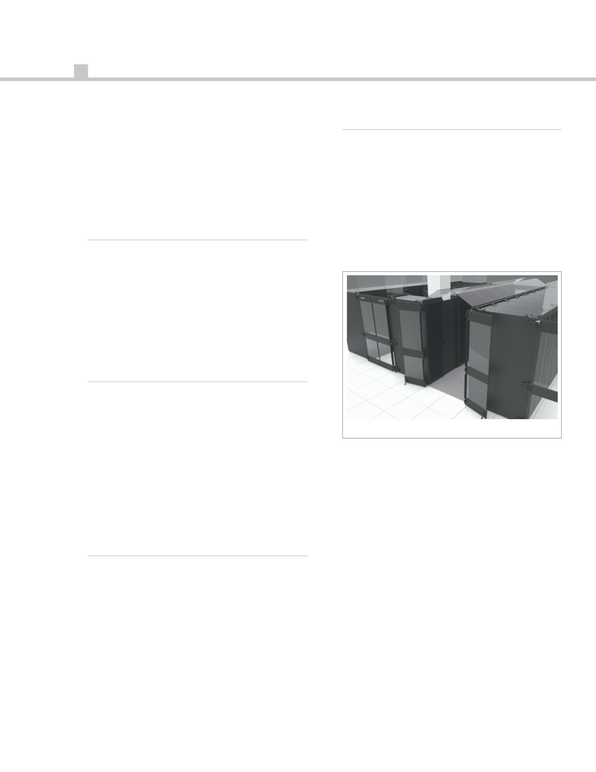
Figure 1 shows the basic principles of a Modular
Containment System. Containment in any computer
room is best attained when there is a structured hot
aisle/cold aisle layout. Specifically, when each
equipment row has an equal length so the ends of the
aisles can be effectively sealed with a pair of
Bi
‑
Directional Doors. While this is the ideal
configuration, significant benefits can be realized
from installation in other configurations such as a
single row aisle, standalone equipment, legacy layout,
rows of different lengths, etc.
Modular Containment is designed as a non-sealed
architecture for hot and cold aisle containment. A
non-sealed architecture is of benefit since there is
considerable variation in the volume of air required by
IT equipment. Even with highly refined airflow
management, a slight excess volume of conditioned
air is delivered to the cold aisle. This is primarily done
to accommodate variations in IT equipment airflow
volume demands. A slight excess airflow volume is
also the result of having redundant cooling capacity
running in the room so when a cooling unit fails there
is still a sufficient volume of conditioned air available.
If there is no opening for the excess volume to escape,
excessive pressure can develop in the cold aisle.
Fig. 1 – Modular Containment System


