
67
WWW.7X24EXCHANGE.ORGcirculation. regardless of the airflow
management effectiveness in the
data center, the it equipment airflow
temperature rise will be the
constant
1
.
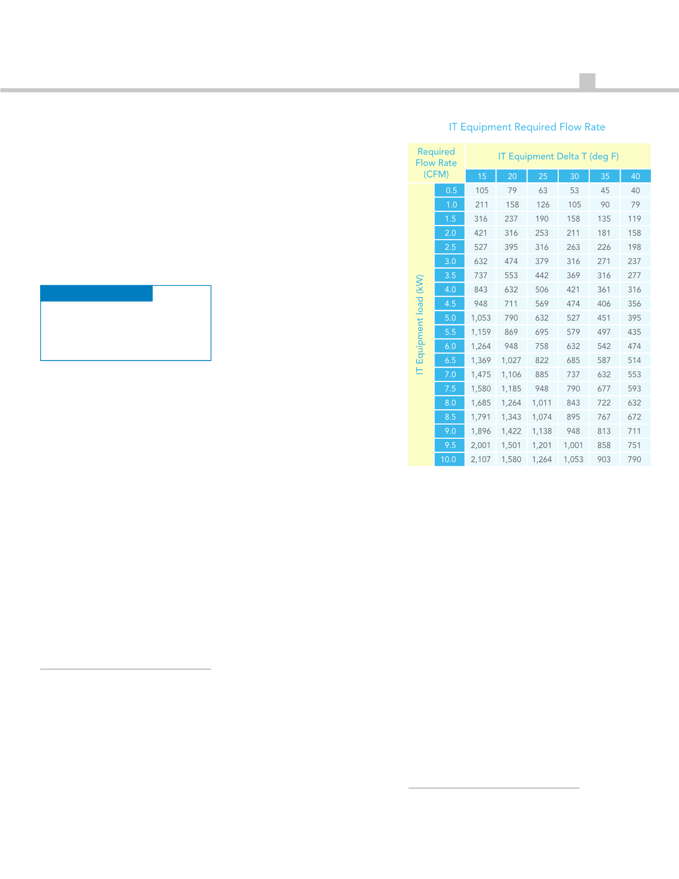
table 1 charts the fixed relationship
between airflow, temperature
differential and heat within the data
center. the following equation is
used to establish these values:
Δt = 3.1W ÷ cfM
in this forMula:
• 3.1 is a constant coefficient at sea level
• W = watts
• CFM = cubic feet per minute airflow
the coefficient changes for
calculations at higher altitudes and in
Celsius, for airflow measurements in
liters per second or cubic meters per
hour, and for heat measured in kw or
btu. regardless of the unit of
measure being considered, there is a
fixed relationship between these
three factors. in practicable
applications, the Δt across it
equipment typically ranges from
around 20˚f up to around 35˚f,
depending on the type of
equipment. for example, blade
servers typically produce a higher Δt
than traditional rack mount servers.
Commonly Known
ΔT: Through
Cooling units
(#3 in Figure 1)
the other established data center Δt
occurs across cooling units. ideally,
this delta should be the same as the
delta across the it equipment,
indicating that the cooling resource
is in sync with the heat load it serves.
unfortunately, due to several factors
this is rarely the case. in legacy
direct expansion (dX) CraC units,
there is typically little allowance for
variation from baseline Δt. for
example, increases in return air
temperature often result in an
associated increase in supply air
temperature, so a 5˚f increase in
return air temperature might result in
a 3˚f or 4˚f increase in the supply
temperature. this results in the
overall Δt increasing slightly, but
nowhere near the proportion
possible with water-cooled coils.
Modern water-cooled Crah units
can remove heat equivalent from a
45˚f to 65˚f temperature drop across
the cooling coils. Given the
mathematical relationship between
heat, airflow and Δt previously
discussed (CfM = 3.1w/Δt), the
higher Δt across those coils equates
to removal of more heat, which
results in the Crah unit operating
much more efficiently. under most
circumstances increased efficiency is
welcome. however, if the Δt across
the it load is still only 20˚f, then
excess heat is not effectively being
removed. instead, the inefficiency of
the overall airflow management
scheme is being accommodated,
which is only a short-term solution.
the Δt across the cooling source is
also affected by set points. for
example, if there is a great deal of
bypass airflow in the data center, it is
possible that the return air can
actually be below the set point and
therefore returned to the data center
without any additional heat being
removed (Δt = zero). further, with a
standard return set point established
(similar to a home or office
thermostat setting), the Crahs will
be working to bring the data center
temperature down to that set point,
resulting in Δt’s which could range
from 0˚f to over 20˚f. finally, if the
Crahs are operating with a fixed
supply temperature, the Δt could
range from 20˚f to 35˚f based on the
types of servers deployed in that
space or the cooling coils could see
less than 10˚f if there is wasted
surplus cooling in the space (up to
over 40˚f if there is a cumulative hot
air re-circulation effect).
The less Commonly
Known DelTa T’s
beyond these well-established Δt’s,
there remains two hidden areas of
Δt that can help data center
owner/operators understand the
differences between it and cooling
coil Δt’s and suggest possible
remediating strategies. these are:
from cooling unit to front of it
equipment (#4 in figure 1) and from
exhaust back to cooling unit (#2 in
figure 1).
often ignored ΔT:
from Cooling unit
to front of iT
equipment
(#4 in Figure 1)
the Δt between the cooling unit
supply output and the server inlet is
Table 1: Relationship between airflow and ΔT


